Launching systems
1. Looping:
The funnel:
The funnel consists of two concentric elements: a rectangular, u-type guiding track made of a stainless steel foil and 5 mm high aluminium walls which is embedded in a preformed quarter ellipse fabricated from a glass fibre soaked epoxy compound. This part is aligned and fixed inside a d = 200 mm vacuum tube. Functionally, there are two planes to consider, the plane of the horizontal centrifuge scatter (+/- 3° at v = 240 m/s decreasing to +/- 1° at v = 1200 m/s) and that of the vertical centrifuge scatter (+/- 0.25°) corresponding to the elliptic plane. The horizontal scatter led to the design of convex walls diverting in the first part to follow the scatter (up to 100 mm) and leading to a 6 mm wide exit.
This shape ensured to maintain a chosen pellet impact angle throughout the funnel length. An exact angle of 1.7° was determined by tailoring the funnel length to fill a quarter of an ellipse (L = 4.76 m) in order to simplify the realization of the guide tube segment. Regarding the vertical scatter a maximum radius of curvature at the ellipse entrance had to be traded against the overall guiding track length. The radius of R = 3.3 m was chosen resulting in a radial impact angle of < 1.4°.

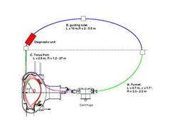
The guide tube segment:
For the guide tube segment a 4.3 x 10.7 mm u-type microwave guide is used, which is made from copper. The tube is anchored in an CF 40 vacuum tube and bended on a elliptically prepared wood frame. The segment is separated from the funnel by a vacuum valve creating a free flight zone of 40 mm. Alignment between the funnel exit tangent and the tube entrance is controlled not to exceed 0.1 mm by a vacuum-tight micropositioner. This allows to keep the radial entry impact angle very shallow despite a radius of R = 2 m. The 9 m long segment is followed by a 1 m diagnostic section situated as close as possible to the plasma. This unit is part of the permanent track connected to the tube via interchangeable couplings. The diagnostics incorporate a double light barrier and shadowgraphy complex.

The tokamak port segment:
The tokamak port segment ( 5 x 5 mm u-type-profile) puts extreme stress on the pellet with curvature radii changing between 25 and 1.5 m because of the specific port geometry (2 m long, 50 mm ID) and an poloidal injection angle of 72°.

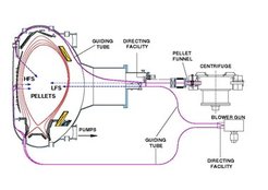
The first step was the injection directly from the outside of the tokamak, into the magnetic low side (LFS) using a centrifuge at pellet velocities from 240 m/s to 1000 m/s. After that, narrow bended tracks were applied in the vessel but were not found capable of high speed launch.
It was postulated that an improvement in refueling-efficiency could be achieved if the injection was realized from the magnetic high field side (HFS). A proof of principle was done: Pellets were injected from the LFS and the HFS with a blower gun at a pellet velocity of 240 m/s. The results confirmed the assessments. In order to reach higher repetition-rates the experiment was reapeated with the centrifuge and an guiding system. Due to the high forces applied to on the pellets during the flight through the tube, the guiding system had to be improved.
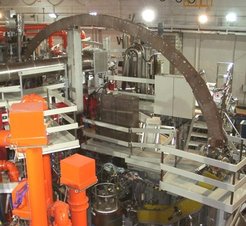
A new complex injection setup employing a looping geometry was built for the HFS of ASDEX Upgrade. A major constraint for the design was the location of the technically complex ASDEX Upgrade centrifuge, which was found to be virtually unmovable. The only feasible option was a rotation of the centrifuge by 180 degree such that pellets are accelerated away from the tokamak and then guided back to the torus HFS side by a roughly elliptical track.
2. Centrifuge:

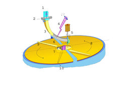
1: Extrusion Cryostat
2: Extrusion Nozzles
3: Storage Cryostat
4: Lever
5: Cutting piston
6: Fuel rod
7: Stop cylinder
8: Acceleration way
9: Outer Acceleration arm
10: Pellet exit