Centrifuge launcher
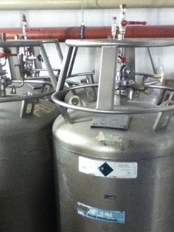
Gas supply system:
The gas supply system consists on gas bottles containing high purity He,H2,D2. He, H2, D2 and He. Helium is used for ventilating the complete system, and H2 or D2 for fueling the extrusion cryostat. The system gives also the possibility of admixing small amounts of Ne to the fueling gas. That allows for example the investigation of how impurities are propagated into the targeted plasma.

Cryostat system: pellet production:
The cryostat system comprises two parallel systems, one for the extrusion cryostat and the other for the storage cryostat. Main caracteristics of the cryostat system:
- The temperature control is based on the pressure difference between the cryostates in the liquid-helium circuit. It is possible to change the temperature of the extrusion cryostat by a controlled electric heating.
- The helium flux is controlled by pressure and flux measurements; the mean consumption is about 5 l/h per cryostat.
- Extrusion is performed with a hydraulic piston.
- All valves are controlled electropneumatically in order to ensure galvanic separation of the different circuits.
- A combination of three doubleacting pistons shifts the extrusion nozzle to 4 positions, namely for three pellet cross-sections and the closed position for fueling the extrusion cryostat.


As concerns the pellet production, first the pellet material is frozen in the extrusion cryostat at a temperature of around 4 K. The solid fuel material is then conditioned by varying the temperature and pressure. By applying about 7 K for H2 and 13 K for D2 and a pressure from 180 to 200 bar, the material is extruded through the nozzle, which determines the quadratic cross-section of the fuel rod produced. This 192 mm long rod is now stored at the appropriate temperature (4 K for H2 and 6 K for D2) in the storage cryostat, which contains a separate channel for each different pellet size. The rigid solid (WEG) fuel rod is pushed by a lever driven by a stepping motor through the exit of the storage cryostat. The number of steps determines the pellet length; That is to say, the length of the pellet can only be increased by steps of 0.25 mm. The extrusion nozzle and the storage cryostat can both be moved pneumatically inside the vaccum system to select the pellet size.
The pellet feed-in procedure in the centrifuge turned out to be critical for the pellet injection. It can decisively determine the angle at the exit of the centrifuge. Futhermore, pellet impacts within the rotating acceleration guide has to be limited to velocities smaller than 50 m/s. This value limits the transversal velocity for a given feed-in radius with respect to the acceleration path.
If a pellet request signal arrives, first the step motor pushes out part of the fuel rod the preselected length . Then, the electronic control system brings the cutting knife into action with a delay time in order to synchronize the cutting and the centrifuge rotation so that it can feed in the pellet at the exact time. The cutter itself moves perpendicularly to the pushing direction of the rod and accelerates the pellets to velocities of about 4 m/s. It is thus ensured that the pellets cover the distance of 15 mm straight down to the acceleration guide within one revolution of the centrifuge.
Pellet acceleration:
The pellet acceleration is realized through a two step acceleration. Pellets are accelerated by the inner driving blade on the disk to the static stop cylinder with a maximum impact velocity of 35 m/s. They slide along the cylinder, and then are stabilized and fixed by little whips to the exit erture of about 60°. This aperture determines the start of the radial main acceleration in the outer acceleration arm.
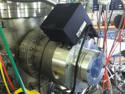
Driver pump and vacuum system:
The driver pump selected for the centrifuge is a Pfeiffer TPH 5000 turbomolecular pump, which has several favourable features. The rotating part of this pump has very large axial inertial moment compared with that of the acceleration arm (factor 20) and can be balanced very precisely in an upper and lower plane without acceleration arm. The latter was balanced separately together with its hub. Finally, the two were balanced together with a residual imbalance of 100 g mm², which ensures a long life of the bearings. Nevertheless, during operation and stand-by, the oscillation behaviour is continuosly controlled.

The driver pump is also stable in case of accidental thermal breakdown of the cryostat system, which may cause a sudden gas release of about 1 bar litre for a few seconds. The pressure in the vessel containing the whole centrifuge system can rise up to about 3 mbar and subject the rotor to lifting forces of about 100 N. The resulting axial motion is limited to 0,1 mm by the heavy weight of the total rotor and. The duration of such a pressure pulse is limited to about 3 s by the combined pumping system. The same is valid if the vessel exit valve is closed and all accelerated pellets hit the vessel wall. Such short pressure pulses do not heat up the rotor and the cryostates to unstable conditions. The vacuum pump contains the Pfeiffer TPH 5000 rotor drive serving for high-vacuum pumping with a speed of 5700 l/s for H2 at full frequency. A Roots blower with 2000 m³/h and a rotary vane pump with 120 m³/h in series provide the backing vacuum.

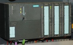
Local control unit:
System contol and data aquisition are performed by a computer system constisting in a Siemens Simatic S7 and a WinCC. Simatic is an automation system developed by Siemens. This system enables machines to run automatically. The user only needs to upload a programm on the Simatic unit and the machine will accomplished the desired function.
Simatic works similar to a digital computer: it can store and run programs. It has also inputs and outputs that can be controlled by the running program. The simatic control unit can collect data from the running machine and act if any parameter is not correct.

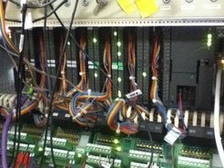
This unit runs the whole process of fuel rod production and also supervises the synchronisation and checks if the delay is appropiate in relation to the cutting signal and the current operation conditions. This way, any desired sequence of pellet injection times can be chosen up to the maximum repetition rate. Moreover, all the relevant parameters such as temperatures, pressures, currents, frequencies and the load on the centrifuge are permanently controlled. In case of pertubation within the system or failure of one of the parts of the apparatus, the control unit brings the whole system to a standstill in an appropriate manner that avoids further damage.